What's the best way to control engine temperature
In-Hose Electronic Fan Controllers.
These Electronic Fan Controllers offer a truly professional solution to the problem of efficiently controlling electric fans on many different types of vehicles.
Revotec Electric Fan Contoller
Featuring the latest surface mount sensor which has no mechanical parts, meaning no parts to wear/fail. The controller gives an instant response to water temperature change, and can be set to switch the fan on at any temperature between 70 and 120°C.
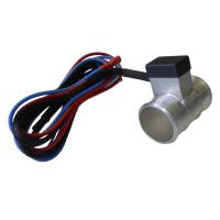
The controller housing (when fitted in to a hose) offers very little obstruction to coolant flow and, as there is no intrusion in to joints as with some fan controllers, this fan controller offers an extra secure, leak free fitment.
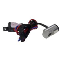
The in-hose electronic fan controllers consist of two main parts: the control unit which is to be mounted in a radiator hose (normally the top radiator hose). Then the fan power relay, which will supply the 12 volt feed for the electric radiator fan. These two main components are connected with a supplied wiring harness.
Installing the Controller
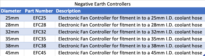
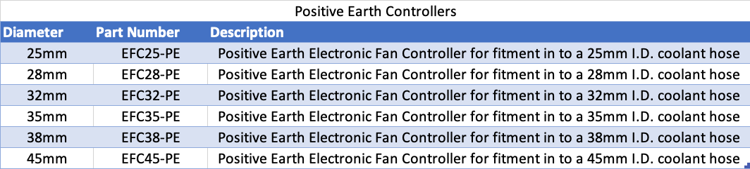
The in-hose fan controller is available to suit 6 different hose diameters, 25mm, 28mm, 32mm, 35mm, 38mm and 45mm. Measure the internal bore of your chosen hose and select appropriate Fan Controller thereon. Choose a position for the controller in a straight section of the hose. Ensure there is sufficient room in the hose to fit the full length of the aluminium housing, which is 65mm long.
Partially drain the cooling system to allow the selected hose to be removed. Using a sharp blade or hacksaw, remove a 20mm section from the hose at the position of which you require the controller.
The two ends of the hose you have just cut can now be fitted to the controller body, ensuring the hose follows the same orientation as it did before being cut. Secure the controller body in position using the hose clamps provided with the kit. Refit the hose to the vehicle, refill the coolant system and check for leaks.
Wiring
The wiring for the Electronic Fan Controllers is a fairly straight forward process and an easy to read wiring diagram is included in the instructions. It is recommended that the live 12 Volt feed is connected via an ignition controlled switch, so the fan will not operate after the ignition has been turned off which can lead to a flat battery.
Fan Controller Adjustment
The fan controller can switch within a temperature range of between 70 and 120°C. Adjustment is carried out via a small adjusting screw located inside the aluminium housing of the unit.
For setting up the controller, start by turning the adjustment screw fully anti-clockwise, this is the lowest setting (70°C). Start the vehicle and get the engine warm. The fan should operate when engine coolant reaches 70°C. Increase (clockwise) the adjuster slowly until the fan stops running. This allows you to check the on/off function of the controller. Continue to increase the adjuster until the fan remains off at normal running temperature. This setting should then switch the fan on if the engine exceeds normal running temperature.
There are three further variations for the Electronic Fan Controllers. We can supply the controllers as male threaded housings, with either M22 or 1/8NPT Thread. These are ideal if the controller is to be fitted in to a radiator or hose adaptor.
Or with 3/8BSP female thread. This allows male/male thread adaptors to be fitted, ideal if being used in oil lines.
And finally, as a self sealing housing, which can be fitted in to the wall of a silicone or rubber hose, utilising technology from the selection of self sealing T-Pieces we have available.
All Electronic Fan Controllers are supplied with Fan Controller unit, 30 Amp Relay, 700mm of associated wiring harness, two hose clamps (where required), fitting instructions and wiring diagram.
Electric Fan Controllers - Part Numbers